Understanding Cantilever Racking System Mechanics: Structural Architecture & Load Distribution
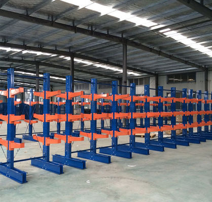
In structural dynamics, a cantilever arm acts as a beam supported at only one end, transferring bending moments directly into the central upright column and base connection. Unlike four-post pallet racks that distribute weight symmetrically across interconnected frames, a Cantilever Racking System must withstand extreme rotational torque and eccentric loading forces.
At IronMax Storage Solutions Co., Ltd., every system is custom-engineered using Finite Element Analysis (FEA) software to calculate exact deflection curves under full load conditions. By adhering strictly to ANSI MH16.1, FEM 10.2.09, and AS4084 international standards, our structural designs protect facility personnel and inventory from structural yield failure or tipping risks.
1. Vertical Column Uprights
Engineered from heavy duty cold-rolled steel profiles or hot-rolled H-Beams (Q235B / Q355B structural grade steel). Punched with high-precision CNC 100mm or 140mm pitch hole patterns, allowing full arm height adjustability without sacrificing column stiffness.
2. Heavy-Duty Base Assemblies
The base unit anchors the entire rack structure securely to the warehouse floor. Welded or heavy-bolted directly to the column, base extensions counteract forward overtum moments and serve as the lowest storage level for direct floor loading.
3. Tapered Cantilever Arms
Available in straight or inclined profiles (2° to 4° tilt). Our arms feature pre-calculated thickness taper to compensate for load flexing. Optional removable pipe stoppers or retaining pins prevent cylindrical goods from rolling off.
4. Rigid Heavy Cross-Bracing
Horizontal and diagonal structural steel bracing sets connect adjacent columns to form a rigid longitudinal frame. Bracing sets absorb axial shear forces created during high-reach forklift loading or seismic activity.
Engineering Information Gain: Calculating Arm Capacity & Deflection Ratios
When selecting a Cantilever Racking System, buyers often make the critical error of assuming load rating is uniform across the arm length. In engineering terms, load capacity is based on a Uniformly Distributed Load (UDL). If a load is placed at the outer tip of the arm, the bending moment on the column flange is doubled!
Formula for Required Arm Count ($N$):
N = \text{Total Bundle Weight (kg)} / \text{Rated Arm Capacity (kg)}
Arm Deflection Limit Standard: According to ANSI MH16.1, maximum allowable arm deflection under full design load must not exceed $L / 180$, where $L$ is the usable arm length. For a 1,200 mm cantilever arm, maximum vertical flex is limited to just 6.6 mm. IronMax Storage Solutions Co., Ltd. designs arms with safety factors of 1.65 to 1.95, keeping deflection well within international safety margins.